What are Festo VZWP magnetic valves and what industrial applications do they serve?
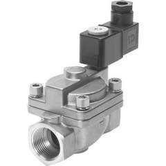
Festo VZWP magnetic valves are electrically actuated solenoid valves designed for precise process and media control in pneumatic and hydraulic systems. These valves serve critical applications in industrial automation, process control systems, and manufacturing equipment where reliable fluid flow control is essential. Industries utilizing VZWP valves include automotive manufacturing, food and beverage processing, pharmaceutical production, and chemical processing facilities. The electric actuation provides rapid response times and precise positioning control, making them suitable for applications requiring frequent switching cycles and accurate flow regulation in pressurized systems.
What are the key technical selection criteria for Festo VZWP solenoid valves?
Selection of Festo VZWP solenoid valves requires consideration of operating pressure range up to 250 bar as indicated in model designations like VZWP-L-M22C-G1-250-V-1P4-40, port connection types including G1 and G3/4 threaded connections, and valve function configurations. The M22C designation indicates the valve body size and mounting pattern, while the voltage rating of 24V DC is standard across the series. Media compatibility must align with seal materials, and the electrical connection type varies between 1P4 single pole and 2AP4/3AP4 multi-pole configurations. Flow coefficient and response time specifications determine suitability for specific process control requirements and cycle frequency demands.
Which international standards and certifications apply to Festo VZWP magnetic valves?
Festo VZWP magnetic valves comply with ISO 9001 quality management standards and meet IEC 60204 electrical safety requirements for industrial machinery applications. The valves conform to EN 60529 ingress protection standards with appropriate IP ratings for industrial environments, and pressure vessel compliance follows EN 12516 standards for valve testing and certification. For explosive atmosphere applications, selected models may carry ATEX certification according to Directive 2014/34/EU, while food-grade applications require FDA compliance for wetted materials. CE marking ensures conformity with European machinery directives, and EMC compatibility follows EN 61000 standards for electromagnetic interference resistance in industrial control systems.
What are the differences between VZWP valve variants with G1, G3/4, N1, and N3/4 designations?
The VZWP valve variants differ primarily in port connection types and mounting orientations, with G1 and G3/4 models featuring BSP threaded connections of 1 inch and 3/4 inch respectively, while N1 and N3/4 variants utilize NPT threaded connections of equivalent sizes. Models like VZWP-L-M22C-G1-250-V-1P4-40 provide G1 BSP connections optimized for European pneumatic systems, whereas N1 variants suit North American installations using NPT threading standards. The pressure rating remains consistent at 250 bar across variants, but flow characteristics vary with port size, with G1/N1 connections providing higher flow capacity than G3/4/N3/4 alternatives. Electrical configurations span from single-pole 1P4 to three-pole 3AP4 connection options across all port size variants.
What are the installation requirements and system compatibility considerations for VZWP solenoid valves?
Festo VZWP solenoid valves require 24V DC electrical supply with appropriate overcurrent protection and must be installed with proper orientation to ensure optimal magnetic actuator performance. System compatibility demands consideration of media temperature range, pressure pulsation limits, and flow direction as indicated by valve body markings, while threaded connections require thread sealant compatible with system media. The M22C mounting pattern provides standardized bolt spacing for manifold integration or individual mounting, and electrical connections via integral cable or connector systems must maintain IP65 protection when properly mated. Pipeline integration requires consideration of valve Cv coefficient for flow calculations and pressure drop analysis, with system filtration recommended to prevent particulate contamination of valve seats and sealing surfaces.
What safety ratings and operating parameters apply to Festo VZWP magnetic valves?
Festo VZWP magnetic valves operate within temperature ranges from -10°C to +60°C ambient and handle media temperatures up to +80°C depending on seal material selection, with maximum operating pressure of 250 bar as indicated in model designations. The valves achieve IP65 ingress protection rating when properly installed with mated electrical connections, providing dust-tight enclosure and protection against water jets from any direction. Safety factor calculations incorporate burst pressure testing at 4 times working pressure according to valve standards, and fail-safe operation depends on spring return mechanisms in normally closed configurations. Electrical safety compliance includes Class I grounding requirements and protection against short circuit conditions through proper system design and overcurrent protection devices rated for 24V DC circuits.
What maintenance schedule and service life expectations apply to Festo VZWP solenoid valves?
Festo VZWP solenoid valves require periodic inspection every 12 months under normal operating conditions, with seal replacement intervals dependent on media type, operating temperature, and cycle frequency, typically ranging from 2-5 years. Service life expectancy exceeds 10 million switching cycles when operated within specified pressure and temperature parameters, with coil insulation monitoring recommended in critical applications. Maintenance procedures include electrical connection inspection for corrosion or loosening, coil resistance measurement to verify within 10% of nominal values, and valve response time verification using appropriate test equipment. Preventive replacement of elastomeric seals should occur before reaching recommended service intervals in applications involving aggressive media or elevated temperatures, while complete valve overhaul or replacement is recommended after 15 years of continuous service regardless of cycle count.
How do different electrical connection configurations affect VZWP valve performance and control integration?
Electrical connection configurations in Festo VZWP valves directly impact control system integration complexity and switching performance, with 1P4 single-pole connections providing basic on/off control for simple applications, while 2AP4 and 3AP4 multi-pole configurations enable position feedback and enhanced diagnostics. The 24V DC coil voltage requirement ensures compatibility with standard industrial control systems and PLCs, with switching current typically 150-200 mA depending on valve size and coil resistance. Response times vary from 15-50 milliseconds depending on electrical configuration and valve size, with multi-pole variants offering faster switching through optimized magnetic circuit design. Connector-type electrical interfaces provide IP65 protection and facilitate field maintenance, while cable connections offer permanent installation benefits but require proper strain relief and conduit protection in industrial environments.
What flow characteristics and sizing considerations determine proper VZWP valve selection for pneumatic applications?
Flow characteristics of Festo VZWP valves depend on port size and internal geometry, with G1 and N1 connections providing flow coefficients (Cv) approximately 30% higher than G3/4 and N3/4 variants at equivalent pressure differentials. Proper valve sizing requires calculation of required flow coefficient based on system pressure drop, media density, and desired flow rate, with oversizing by 25-30% recommended to accommodate system variations. The 250 bar pressure rating enables use in high-pressure pneumatic systems while maintaining linear flow characteristics up to critical pressure ratios, typically 0.5 for air applications. Valve selection must consider downstream pressure recovery requirements and potential cavitation in liquid applications, with flow direction markings on valve body indicating optimal installation orientation for maximum flow coefficient and minimal pressure drop across the valve assembly.