
Loop impedance testing - how do you prove disconnection?
Loop impedance testing proves that the protective device disconnects fast enough during a fault. This guide explains the measuring principle, prospective fault current, the disconnection condition to IEC 60364-4-41/-6 and how to select the right multifunction tester.
View testersWhat is loop impedance and why measure it?
The earth fault loop impedance Zs is the total impedance of the path a fault current follows during an earth fault: from the source through the line conductor to the fault, then back via the protective conductor. From Zs and the nominal voltage U0 you obtain the prospective fault current Ik that must trip the protective device.
The lower Zs is, the higher the fault current and the faster the fuse or circuit breaker disconnects. The test to IEC 60364‑6 (DIN VDE 0100‑600) is part of the initial and periodic verification and proves that protection by automatic disconnection of supply to IEC 60364‑4‑41 actually works.
How do you prove the disconnection condition?
The proof rests on the condition Zs x Ia ≤ U0. Here Ia is the current that trips the protective device within the required disconnection time. The measured loop impedance must therefore be smaller than U0 / Ia.
In a TN system final circuits up to 32 A require a maximum disconnection time of 0.4 s at 230 V, while distribution circuits and larger circuits are allowed 5 s. Read the trip current Ia from the tripping curve: a type B MCB trips magnetically at 5 times, a type C at 10 times its rated current.
- Measure Zs at the most remote point of the circuit - impedance is highest there.
- Compare the measured value with the limit from the tripping curve.
- Allow for temperature correction: warm conductors have higher resistance.
- On RCD-protected circuits use the no-trip loop measurement with a low test current.
How do you measure and document correctly?
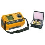
Measurement is done live with a multifunction installation tester: the instrument briefly loads the loop with a defined test current and calculates the impedance from the voltage drop. A reliable contact at L, N and PE of the socket or terminal under test is essential.
On circuits with an RCD a special method using a very small or pulsed test current prevents nuisance tripping of the residual current device. Modern testers still measure the loop with high resolution and display Zs together with the calculated Ik directly.
- Check voltage and phase rotation and inspect the installation first.
- Measure at the most remote point and assign the value to its circuit.
- Record Zs, Ik, breaker type and limit value in the test certificate.
- Keep the tester calibrated and have it checked regularly.
Frequently asked questions
What does the condition Zs x Ia ≤ U0 mean?
It ensures the current flowing during a fault is high enough to trip the protective device within the permitted time. Zs is the measured loop impedance, Ia the trip current and U0 the nominal line-to-earth voltage (230 V).
Which disconnection time applies in a TN system?
For final circuits up to 32 A at 230 V a maximum of 0.4 s, and 5 s for distribution and larger circuits. These limits come from IEC 60364‑4‑41.
How do I measure without tripping the RCD?
Modern installation testers offer a method with a very small or pulsed test current that evaluates the loop without tripping the residual current device.
Why measure at the most remote point?
That is where the conductor run is longest and loop impedance is highest. If the worst-case point meets the disconnection condition, it holds for the whole circuit.
Looking for the right installation tester?
We supply meters for loop impedance and prospective fault current to IEC 60364-6 - with an RCD-friendly measuring method and reporting function.
Standards-compliant
Verification to IEC 60364-4-41 and -6.
Precise measurement
Zs and Ik in high resolution, even behind an RCD.
Documentable
Readings can be stored for the test certificate.
Selection help
We help you choose the right products; technical details are clarified with the manufacturer.