
Redundant 24 V supply with N+1 - how do you build it?
Critical control systems must not go down when a power supply fails. This guide shows how to build a fail-safe 24 V DC supply using a redundancy module and two supplies sized to N+1 - from dimensioning and decoupling to the fault signal.
To the guidesWhat does N+1 redundancy mean for a power supply?
N+1 means: for the load you actually need, N, you install one additional equivalent power supply. If one fails, the remaining unit carries the full load. So a faulty supply cannot short out the healthy one, both feed a common bus through a redundancy module with decoupling.
Without decoupling, an internal short in the failed unit would collapse the shared 24 V bus. The redundancy module isolates the faulty branch through diodes or active MOSFET paths, so the controller keeps running without a voltage dip.
- N = sum of all loads on the 24 V bus (continuous load plus reserve).
- +1 = an identical supply that shares the load in normal operation.
- Both supplies feed together, the module keeps them decoupled.
- Redundancy is not a UPS - it covers device failures, not mains outages.
How do you size the supplies and the module?
Each individual supply must carry the full system load on its own, because in a fault only one remains. For a continuous load of 15 A you therefore pick two supplies rated 20 A each, not 10 A each. The redundancy module must be rated for the sum of both output currents.
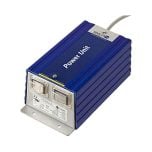
How are the supplies and module wired?
Both supplies feed their outputs into the two inputs of the redundancy module, whose common output feeds the 24 V bus. Set both supplies to exactly the same output voltage, typically 24.0 to 24.3 V, so the load shares evenly between them.
- Fuse supply 1 and 2 individually, ideally on separate feeders.
- Set output voltages equal (deviation below 0.1 V) for even current sharing.
- Keep leads to the module short and well sized - voltage drop distorts sharing.
- Wire the module collective-fault contact to a PLC input.
- Place module and supplies for good heat removal inside the cabinet.
Frequently asked questions
Can I just wire two supplies in parallel?
No. Without decoupling, an internal fault in one supply can short out the 24 V bus and take down both units. The redundancy module isolates the faulty branch through diodes or MOSFET paths.
How big must each individual supply be?
Each supply must carry the full system load on its own, because only one remains in a fault. Plan roughly 1.3x the continuous load as reserve per unit.
Does N+1 replace a UPS?
No. N+1 covers the failure of one power supply, not a mains outage. For mains failures you additionally need a UPS or a DC buffer module.
Why must both supplies be set equally?
Equal output voltage gives even current sharing. If one unit deviates it permanently carries more load and ages faster.
Planning a fail-safe 24 V supply?
Learn more about 24 V power supplies and redundancy modules with diode or MOSFET decoupling, plus collective fault signalling, in our guide.
True redundancy
Decoupling isolates the faulty supply cleanly.
Fault signal included
Volt-free collective fault contact for the PLC.
Correctly sized
Supplies rated for full load in a fault case.
Selection help
We help you choose the right products; technical details are clarified with the manufacturer.